Use this property grid to configure an aggregated carrier of up to five component carriers. To configure the individual component carriers refer to Component Carrier (Advanced LTE-A FDD Downlink).
The Carrier Aggregation node is composed of a carrier aggregation configuration summary table that contains a list of the component carriers. Figure 1 shows these carriers as CC1 and CC2.
The top row of buttons are the Waveform Setup buttons provided again for your convenience in the Carrier Aggregate node.
If you currently are using a carrier aggregation as part of your waveform setup, all of the LTE-A carrier choices are grayed out. Delete the current Carrier Aggregation if you prefer to use a different LTE-A carrier. All of the LTE-A carriers will then be active.
Figure 1 Advanced LTE-A FDD Downlink Carrier Aggregation
|
Carrier Aggregation Configuration Summary Table |
Component Carrier List |
Misc |
|
|---|---|---|---|
|
Buttons |
Settings | ||
This table enables you to view the key parameters for each carrier that is aggregated in the waveform. You can have a maximum of 16 carriers. But, you can only have one carrier aggregate with a maximum of five component carriers (the carrier aggregate and its five component carriers, counts as 1 carrier against the 16-carrier maximum). See the Component Carrier list.
Double-click or use the drop-down list to select Carrier Aggregation Capability, which decides the combination of number of component carrier and system bandwidth.
Choice: On | Off
Default On
Click in the cell and use the drop-down arrow to select either On or Off.
|
On |
The Frequency Offset and Cell ID values are automatically set by the software. The Cell ID is set to the same value as the Component Carrier index number. |
||
|
Off |
Manually set the Frequency Offset and Cell ID values. |
This list enables you to view the key parameters for each component carrier in the aggregated carrier. You can add or delete component carriers using the buttons above the list of component carriers (see descriptions below). You can use a maximum of five component carriers.
Click the Select Predefined Carrier Aggregation (CA) Configuration button  to open a window with a list of pre-defined carrier configurations.
To replace the current aggregate carrier configuration in the setup table with one of these
pre-defined configurations, select the desired configuration and click
or double-click the desired
configuration.
to open a window with a list of pre-defined carrier configurations.
To replace the current aggregate carrier configuration in the setup table with one of these
pre-defined configurations, select the desired configuration and click
or double-click the desired
configuration.
Click the Add Component Carrier (CC) button  to open a
 drop-down list from which you can select a component carrier to add to the setup table. The carrier
can be inserted above or below the currently selected carrier in the table. The maximum
number of component carriers is five.
drop-down list from which you can select a component carrier to add to the setup table. The carrier
can be inserted above or below the currently selected carrier in the table. The maximum
number of component carriers is five.
Option Vxx adds the capability to select an Advanced LTE-A TDD component carrier. Refer the N7625B Signal Studio for LTE/LTE Advanced TDD help for more information.
Click the Delete Component Carrier (CC)
button  to delete the currently selected carrier
in the list of component carriers.
to delete the currently selected carrier
in the list of component carriers.
Click the Copy Component Carrier (CC) button  to quickly add a copy of the selected component carrier
to the component carrier list in the carrier aggregation configuration summary table.
to quickly add a copy of the selected component carrier
to the component carrier list in the carrier aggregation configuration summary table.
There can be up to five component carriers per aggregated carrier.
Click to enable or disable the component carrier selected.
This State parameter and the State parameter on each Component Carrier (CC) node are coupled.
Choice: 1.4 MHz (6RB) | 3 MHz (15RB) | 5 MHz (25RB)) | 10 MHz (50RB) | 15 MHz (75RB) |20 MHz (100RB)
Default: 10 MHz (50RB)
Double-click or use the drop-down menu to set the system bandwidth and number of Resource Blocks (RB). When you select a system bandwidth, the software automatically adjusts the value in the Total number of Resource Blocks cell and the Total number of Occupied Sub-carriers cell.
This System BW parameter and the System BW parameter on each Component Carrier (CC) node are coupled.
The resource blocks and some parameters are reconfigured by changing the System Bandwidth parameter, similar to when a is executed.
Default: 0.000000 Hz
Sets the frequency offset for the carrier relative to the signal generator’s frequency setting.
The range of the parameter is coupled to the Oversampling Ratio, the Base Sampling Rate, the System Bandwidth and the max ARB Sample Clock of the connected signal generator.
Frequency Offset is always editable, even if Auto Carrier Aggregation Configuration is on.
In the case (1) or (2), auto configuration is done for Frequency Offset and Cell ID.
(1) When any action "Add CC" or "Delete CC" or "Copy CC" or Change System BW is done and Auto Carrier Aggregation Configuration parameter is On.
(2) When Auto Carrier Aggregation Configuration parameter is changed to On from Off.
Auto configuration sets Cell ID same as Component Carrier Index.
If Auto Carrier Aggregation Configuration is set to off, auto configuration does not work.
Range: 0–503
Default: 0 with Auto Carrier Aggregation Configuration set to Off
Same as the CC index number with auto Carrier Aggregation Configuration set to On
With Auto Carrier Aggregation Configuration set to Off, enter a cell ID value.
The software uses this value to set the Physical Layer Cell ID group and sector cells:
Cell ID = (3 x Physical Cell ID group + Physical Cell ID sector).
This property is also available in the Downlink node.
Click the cell to assign a Component Carrier (CCn)as the primary cell. In carrier aggregation, only one component carrier can be selected. If the primary cell carrier is deleted or its State changes, the software automatically sets a another component carrier as the primary cell.
Secondary Cell Range: 1 to 7
Sets the Serving Cell Index for the component carrier.
The primary cell is always set to 0 and cannot be changed.
The secondary cell Serving Cell Index can be set to a value in the range.
The software automatically sets the primary cell to 0. If the primary cell selection changes to another component carrier, the software automatically changes that carrier's Serving Cell Index to 0 and renumbers the Serving Cell Index for the others.
Refer to 3GPP TS 36.211, 36.212, 36.213, and 36.331.
Choices: checked (on) | unchecked (off)
Default: unchecked (off)
Set whether to use ABS (almost blank subframe) for each component carrier by clicking the check-box:
|
|
unchecked (off) |
|
ABS is disabled and its related settings are inactive (nothing shows). |
|
|
checked (on) |
|
ABS is available for the component carrier and its related settings are active. |
When the component carrier ABS state is on, the Transmission Configuration Length for all DL-SCH becomes a read-only value that is set to the same length as the Waveform Generation Length.
This property is also available in the Downlink node.
Coupling: Inactive until ABS is checked
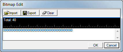
Set the ABS bit pattern for the corresponding component carrier by double-clicking on User Bits (n). This launches the Bitmap Edit dialog box that is used to enter up to 40-bits.
Each bit position represents a subframe. Use the keyboard to enter either a 0 or a 1.
|
|
0 |
|
ABS is not applied to the subframe. |
|
|
1 |
|
ABS is applied to the subframe. |
Within the Bitmap Edit dialog box are the two buttons Import and Export.:
Import allows the loading of a previously saved bitmap.
Export allows the saving of the current bitmap.
The first position of the ABS pattern corresponds to subframe 0 where SFN = 0. The ABS pattern is continuously repeated during the Transmission Configuration Length of the DL-SCH. For example, if the Transmission Configuration Length is 120 ms and there are 30-bits in the ABS pattern, the ABS bit pattern would repeat four times.
Per the 3GPP standards, ABS is designated as protected from inter cell interference from the sending eNB.
This property is also available in the Downlink node.
Choices: checked (on) | unchecked (off)
Default: checked (on)
Coupling: Inactive until ABS is checked
Click the check-box to either enable or disable PSS/SSS during the ABS for the corresponding component carrier.
This property is also available in the Downlink node.
Choices: checked (on) | unchecked (off)
Default: checked (on)
Coupling: Inactive until ABS is checked
Click the check-box to either enable or disable PBCH during the ABS for the corresponding component carrier.
This property is also available in the Downlink node.
Choices: Inter-band 1 | Inter-band 2
These parameter choices are only displayed if you have chosen one of the Inter-band hardware setups. Determines the RF band (inter-band) and the antenna that each component carrier's settings are applied to.
The graph view displays several different representations of the generated waveform. For more information, see Graph View